In RF, microwave, and high-speed digital applications, standard FR-4 materials fail to deliver the necessary electrical performance. This Rogers PCB Material Guide for the RO4000 & RO3000 Series provides the definitive technical comparison for engineers designing antennas, power amplifiers, radar systems, and 5G infrastructure. Choosing the right laminate is critical for signal integrity and thermal management.
RO4000 Series: The Workhorse of High-Volume RF — Rogers PCB Material Guide
The RO4000 series combines low-loss electrical performance of PTFE with the manufacturing ease of FR-4, making it a cornerstone of any Rogers PCB Material Guide.
Core Technology & Manufacturing Benefits of RO4000 Laminates
Based on woven glass-reinforced hydrocarbon/ceramic thermoset resin, the RO4000 series requires no special processing. Unlike PTFE, these materials do not need plasma etching for hole wall preparation. They can be processed using standard epoxy/FR-4 PCB fabrication processes, including standard drilling, routing, and direct-plating. They exhibit excellent thermal stability with CTE closely matching copper, ensuring high reliability in multi-layer designs, particularly in lead-free reflow soldering. The woven glass reinforcement provides superior dimensional stability, making them ideal for tight registration and complex multi-layer stacks.
Key Material Grades: RO4350B vs. RO4003C
The two flagship grades in this series are RO4350B and RO4003C.
RO4350B (The Industry Standard): Dk is 3.48 ± 0.05 at 10 GHz, with a tight tolerance critical for precise impedance control. Df is 0.0037 at 10 GHz, a low-loss figure suitable for power amplifiers and base station antennas. It offers excellent thermal conductivity at 0.62 W/m/K and robust mechanical properties, making it the default choice for commercial RF applications.
RO4003C (The Low-Loss Alternative): Dk is 3.38 ± 0.05 at 10 GHz. Df is 0.0027 at 10 GHz, lower than RO4350B, making it better suited for higher-frequency bands. It offers lower electrical loss but slightly lower thermal conductivity at 0.55 W/m/K, often chosen for sensitive receiver circuits.
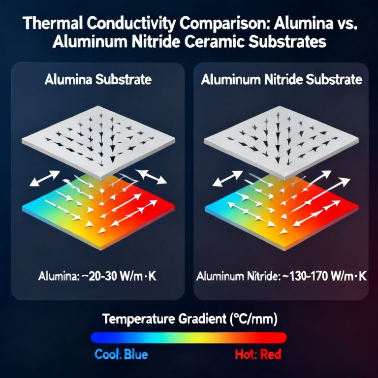
Thermal Management & Multi-Layer Construction with RO4000
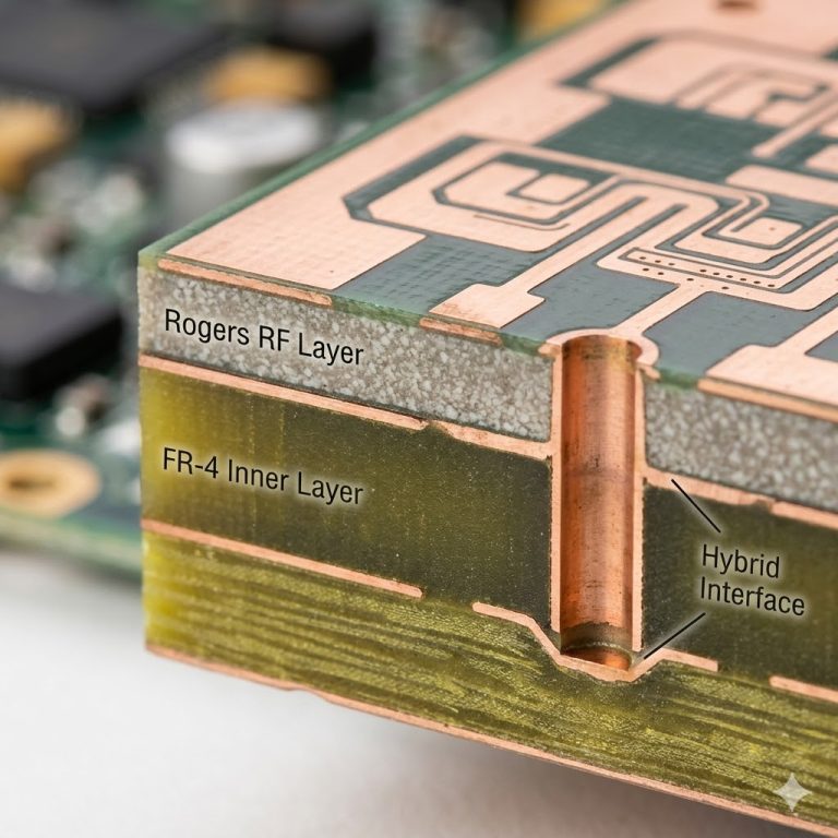
The RO4000 series is designed for robust multi-layer builds. Engineers often pair RO4350B with RO4450F or RO4450T bonding prepregs, which have a similar Dk, ensuring a homogeneous dielectric stack. Thermal conductivity at 0.62 W/m/K for RO4350B is significantly higher than standard FR-4 (~0.3 W/m/K), allowing for better heat dissipation from high-power RF components. The material is fully compatible with lead-free soldering temperatures up to 260°C.
Typical Applications for RO4000 Series
- Cellular Base Station Antennas: Common for 4G/LTE and 5G massive MIMO arrays.
- Power Amplifiers (PAs): Combination of low loss, good thermal conductivity, and reliable FR-4 processing.
- Automotive Radar: For 77 GHz and 24 GHz sensors, RO4003C is often preferred for its lower loss at mmWave frequencies.
- RFID Tags & Readers: Low cost relative to PTFE materials makes it suitable for high-volume commercial products.
- Microwave Backhaul & Satellite Communications: Where high reliability and consistent performance over temperature are required.
RO3000 Series: The High-Performance PTFE Family — Rogers PCB Material Guide
The RO3000 series represents Rogers’ high-end PTFE-based laminates, designed for applications demanding the lowest possible electrical loss and most stable dielectric constant over a wide frequency range, particularly at mmWave frequencies. This section of the Rogers PCB Material Guide focuses on ultra-low loss performance.
Core Technology & Material Composition of RO3000 Laminates
Unlike the hydrocarbon/ceramic resin of the RO4000 series, the RO3000 series uses a ceramic-filled PTFE composite. PTFE is inherently a very low-loss material. The ceramic filler controls Dk and CTE while maintaining low loss. These materials are engineered to have very stable Dk over a wide temperature range (typically ±20 ppm/°C or better), critical for phase-sensitive applications like phased-array antennas. Because it is PTFE-based, the RO3000 series requires specialized fabrication processes, including plasma etching or sodium etching to ensure reliable copper plating adhesion.
Key Material Grades: RO3003, RO3010, and RO3035
The RO3000 series offers a range of Dk values to match specific design needs.
RO3003 (The Ultra-Low Loss Champion): Dk is 3.00 ± 0.04 at 10 GHz. Df is 0.0010 – 0.0013 at 10 GHz, exceptionally low loss tangent, making it one of the best materials for high-Q circuits. It is often used as a core material in multi-layer boards for high-reliability military and aerospace applications. Its low Dk is ideal for wide-bandwidth designs.
RO3010 (The High-Dk Option): Dk is 10.2 ± 0.30 at 10 GHz. Df is 0.0022 at 10 GHz. This material is specifically designed for size reduction, allowing for smaller circuit dimensions crucial for miniaturized devices like patch antennas for GPS or small-form-factor power dividers.
RO3035 (The Balanced Performer): Dk is 3.50 ± 0.05 at 10 GHz. Df is 0.0015 at 10 GHz. It offers a good balance between low loss and a Dk similar to RO4350B, often used when a designer needs lower loss than RO4000 but wants a familiar Dk value.
Thermal & Mechanical Properties of RO3000
Thermal conductivity is generally lower than the RO4000 series, typically around 0.50 W/m/K for RO3003, which can be a limitation in high-power designs unless thermal vias are used. The ceramic filler gives these materials a very low and stable CTE, matching copper well in the Z-axis, which is excellent for plated through-hole reliability. Some grades, like RO3003, can be supplied in thin, flexible formats, enabling the design of conformal antennas.
Typical Applications for RO3000 Series
- Millimeter-Wave (mmWave) 5G & Radar: The extremely low loss of RO3003 is essential for 77 GHz automotive radar and 28 GHz 5G phased arrays.
- Satellite Communications (SatCom): High reliability, low loss, and stable Dk over temperature are critical for space-grade hardware.
- Military & Aerospace (EW, ECM, Radar): High-reliability circuits requiring consistent performance in harsh environments.
- High-Speed Digital Test Equipment: Where signal integrity at very high data rates (e.g., 100 Gbps) is paramount.
- High-Q Filters & Couplers: The low loss tangent allows for very high unloaded Q factors.
RO4000 vs. RO3000: Technical Comparison Table
| Rogers PCB Material Guide Feature | RO4000 Series (e.g., RO4350B) | RO3000 Series (e.g., RO3003) |
|---|---|---|
| Resin System | Hydrocarbon / Ceramic (Thermoset) | Ceramic-Filled PTFE (Thermoplastic) |
| Loss Tangent (Df) | 0.0037 (Low Loss) | 0.0010 – 0.0013 (Ultra Low Loss) |
| Dk Tolerance | ±0.05 (Very Tight) | ±0.04 (Tightest) |
| Dk Stability vs. Temperature | Good (±40 ppm/°C) | Excellent (±20 ppm/°C or better) |
| Fabrication | Standard FR-4 Process | Requires PTFE-specific process (Plasma etch) |
| Cost | Moderate (Cost-effective for high volume) | High (Premium material for high-performance) |
| Thermal Conductivity | 0.62 W/m/K (Good) | 0.50 W/m/K (Moderate) |
| Primary Use Case | High-volume commercial RF (4G/5G Base Stations) | High-performance, low-volume, mmWave & aerospace |
When to Choose RO4000?
You are designing a commercial product with a tight budget. You need high-volume, fast-turnaround fabrication. You are working at frequencies up to 20-30 GHz. You require good thermal management for power devices. Your PCB manufacturer is not specialized in PTFE processing.
When to Choose RO3000?
You are designing for frequencies above 30 GHz (e.g., 77 GHz radar). You need the absolute lowest insertion loss for sensitive receiver paths. Your circuit is phase-critical (e.g., phased-array antennas). You are designing for military, aerospace, or space applications. You can afford the higher material cost and specialized fabrication.
Design & Fabrication Best Practices for Rogers Laminates
To successfully implement Rogers materials, follow these best practices from the industry’s leading sources. Always use a prepreg with a matching Dk to your core material. For RO4000, use RO4450F/T. For RO3000, use RO3001 bonding film. Because of the tight Dk tolerances, you can achieve very precise impedance control; provide your PCB manufacturer with the exact Dk values and tolerances from the Rogers datasheet. For drilling, RO4000 accepts standard carbide drills, while RO3000 requires slower feed rates and higher spindle speeds to avoid smearing the PTFE. For plating, RO4000 can be direct-plated, but RO3000 requires a sodium etch or plasma treatment to activate the PTFE surface before direct metallization. Failure to do this will result in copper peel-off. Standard liquid photoimageable (LPI) solder masks adhere well to RO4000, while RO3000 may also require a plasma treatment before solder mask application. PTFE materials are softer and can be easily scratched or dented, so handle panels with care and use clean, sharp cutting tools.
Key Terminology in High-Frequency PCB Design
Dielectric Constant (Dk): A measure of a material’s ability to store electrical energy in an electric field, critical for impedance control. Dissipation Factor (Df): Also known as loss tangent, it quantifies the energy lost as heat in the dielectric material. Lower Df means less signal loss. CTE (Coefficient of Thermal Expansion): The rate at which a material expands with temperature, important for reliability in multi-layer boards. mmWave: Millimeter-wave frequencies, typically 30 GHz to 300 GHz, requiring ultra-low loss materials like RO3003.
Frequently Asked Questions about Rogers PCB Material Guide
What is the main difference between RO4000 and RO3000 series in this Rogers PCB Material Guide?
The main difference lies in the resin system and loss performance. The RO4000 series uses a hydrocarbon/ceramic thermoset that processes like FR-4, offering low loss (Df 0.0037) at moderate cost. The RO3000 series uses ceramic-filled PTFE for ultra-low loss (Df 0.0010), requiring specialized fabrication, and is best for mmWave applications.
Which Rogers material is best for 77 GHz radar PCB design?
For 77 GHz radar PCB design, the RO3000 series, particularly RO3003, is the best choice due to its ultra-low loss tangent (0.0010) and excellent Dk stability over temperature, which are critical for high-frequency radar performance.
Can RO4000 series be used for 5G base station antennas?
Yes, the RO4000 series, especially RO4350B, is widely used for 5G base station antennas. It offers a good balance of low loss, thermal management, and cost-effectiveness, and can be processed with standard FR-4 manufacturing lines.
Does the RO3000 series require special PCB fabrication processes?
Yes, because the RO3000 series is PTFE-based, it requires specialized fabrication processes such as plasma etching or sodium etching for hole wall preparation before plating, and adjusted drilling parameters to avoid smearing.
What is the typical Dk value for RO4350B in this Rogers PCB Material Guide?
The typical Dk value for RO4350B is 3.48 ± 0.05 at 10 GHz, providing tight tolerance essential for precise impedance control in high-frequency designs.