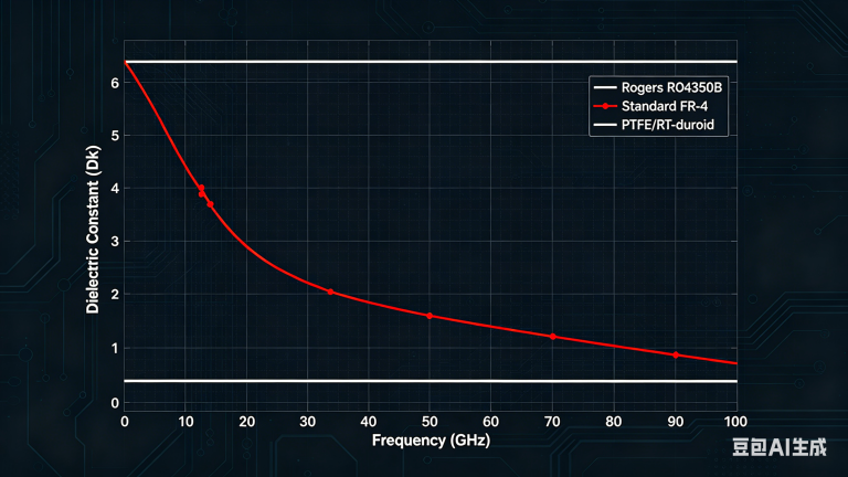
This PTFE PCB material guide provides a deep dive into low-loss high-frequency laminates, essential for RF, microwave, and millimeter-wave electronics where signal integrity is paramount. As frequencies climb into the GHz range, standard FR-4 materials become a liability due to their high dielectric loss, inconsistent Dk, and poor thermal stability.
PTFE-based laminates are engineered to minimize signal attenuation, maintain a stable impedance, and perform reliably across extreme temperatures and harsh environments. This comprehensive guide synthesizes the most trusted industry knowledge to help you select, design with, and manufacture PTFE PCBs for applications ranging from 5G base stations to aerospace radar systems.
What is PTFE and Why is it Used for High-Frequency PCBs?
PTFE PCB Material Chemistry
PTFE (Polytetrafluoroethylene) is a synthetic fluoropolymer of tetrafluoroethylene. Its unique molecular structure—a carbon backbone fully shielded by fluorine atoms—gives it exceptional properties: it is chemically inert, hydrophobic, and has one of the lowest coefficients of friction of any solid. For PCB applications, this translates into:
- Lowest Dielectric Constant (Dk): Typically 2.1–2.5, depending on filler materials. This allows for thinner dielectrics and tighter impedance control.
- Extremely Low Dissipation Factor (Df): Often below 0.002 at 10 GHz. This is critical for reducing signal loss at high frequencies.
- Excellent Thermal Stability: Dk and Df remain nearly constant across a wide temperature range (e.g., -55°C to +200°C), ensuring reliable performance in thermal cycling.
- Low Moisture Absorption: PTFE absorbs less than 0.1% water by weight, preventing performance degradation in humid environments.
Primary Applications for PTFE Laminates
PTFE PCBs are not for every project. They are reserved for applications where signal loss must be minimized and reliability is non-negotiable:
- 5G/6G Infrastructure: Antenna arrays, beamforming modules, and small cells require low-loss laminates for high efficiency.
- Aerospace & Defense: Radar systems, satellite communications, and electronic warfare equipment demand stable performance under extreme conditions.
- Automotive Radar: 77 GHz automotive radar sensors rely on PTFE for consistent Dk and low loss.
- Medical Devices: High-frequency imaging and diagnostic equipment (e.g., MRI, ultrasound) benefit from PTFE’s low signal degradation.
- High-Speed Digital: SerDes, backplanes, and data center interconnects operating at 25 Gbps+ often use PTFE hybrids to maintain signal integrity.
Key Material Properties of PTFE Laminates
Understanding the key performance parameters is essential for selecting the right laminate. Below is a detailed breakdown of the critical properties, sourced from the most authoritative industry guides.
Dielectric Constant (Dk) and Dissipation Factor (Df)
PTFE’s pure Dk is around 2.1. Manufacturers add ceramic fillers (e.g., silica, woven glass) to increase Dk to values like 2.2, 2.6, 3.0, or 3.5 for specific impedance targets. Look for laminates with tight Dk tolerance (e.g., ±0.02 or ±0.05) to ensure consistent impedance across the board. The dissipation factor (Df) is the primary metric for high-frequency loss. Pure PTFE has a Df of 0.0002–0.0005 at 10 GHz. Filled PTFE laminates typically range from 0.001 to 0.004. For frequencies above 10 GHz, choose a laminate with Df ≤ 0.002. The Temperature Coefficient of Dk (TCDk) for high-performance laminates is less than 50 ppm/°C, ensuring stability over -55°C to +150°C.
Thermal Properties
Pure PTFE has a high CTE (200–300 ppm/°C in Z-axis), which can cause via and pad stress during soldering. Manufacturers reduce this by adding ceramic fillers or woven glass cloth, bringing Z-axis CTE down to 50–70 ppm/°C. Use filled PTFE for multi-layer boards with plated through-holes. PTFE is a thermal insulator (0.2–0.3 W/m·K). For power applications, choose laminates with high thermal conductivity (e.g., 1.0–2.0 W/m·K) from ceramic-filled grades. PTFE does not have a true Tg like FR-4. Instead, it has a melt temperature (~327°C). This means it can withstand lead-free soldering profiles (260°C peak) without degradation, but requires careful handling to prevent delamination.
Mechanical & Processing Properties
PTFE is relatively soft and flexible compared to FR-4. This can be an advantage for flexible circuits but a challenge for rigid boards requiring dimensional stability. Unfilled PTFE can shrink or distort during etching and lamination. Filled or woven-glass-reinforced laminates offer better stability (<0.05% shrinkage). Copper adhesion to PTFE is inherently low. Manufacturers use specialized surface treatments (e.g., sodium etching, plasma treatment) to achieve peel strengths of 6–10 lb/in. Always specify the copper foil type (e.g., reverse-treated, rolled-annealed) for reliable adhesion.
Types of PTFE Laminates: A Comparative Guide
The industry offers several categories of PTFE laminates, each optimized for different performance-cost trade-offs. Here are the main types, based on the most trusted material data sheets.
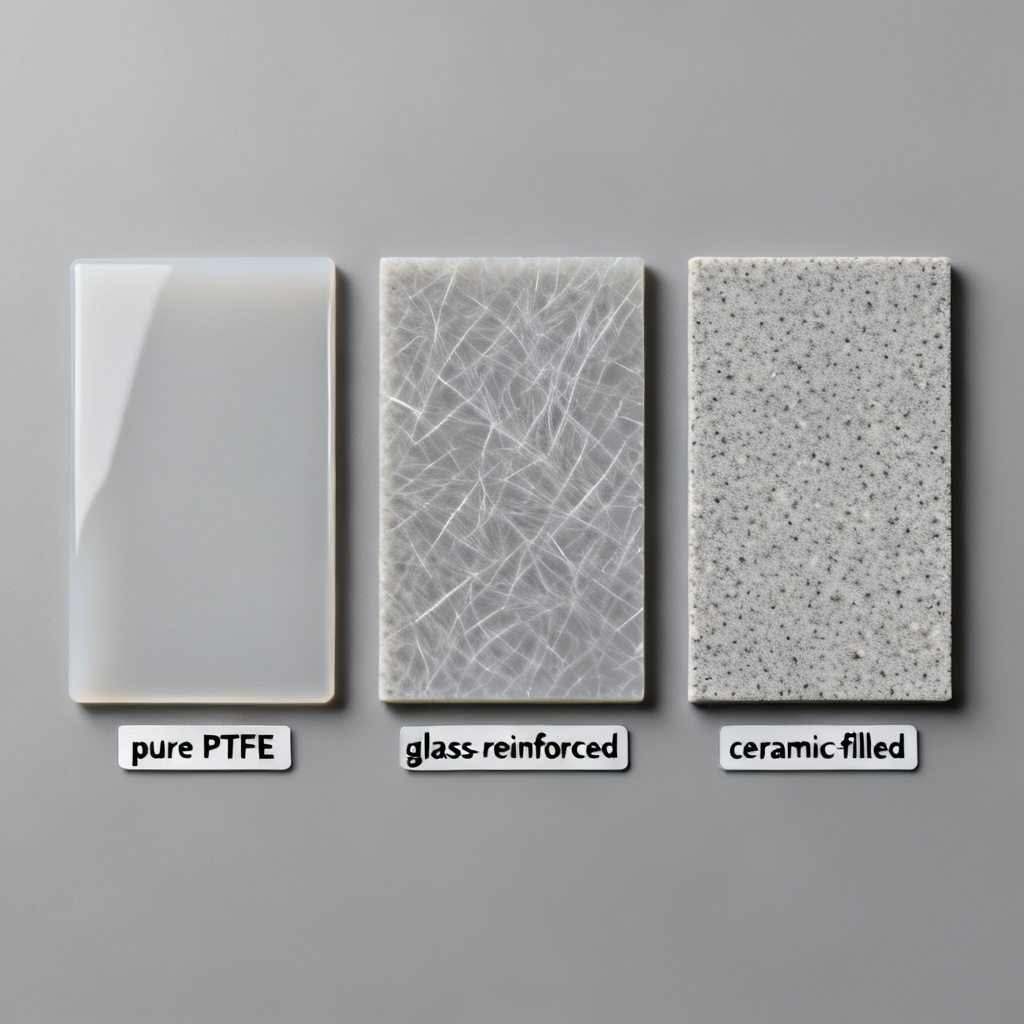
Pure PTFE (Unreinforced)
100% PTFE, no fillers or glass reinforcement. Dk is ~2.1 (very low), Df is 0.0002–0.0005 (extremely low). Advantages include lowest loss, best for >50 GHz applications, and excellent chemical resistance. Disadvantages include very high CTE, poor dimensional stability, and difficulty in processing (requires specialized drilling and etching). Typical brands: Rogers RT/duroid 5880, Taconic TLY-5, Arlon CuClad 217. Best for point-to-point microwave interconnects, waveguide transitions, and test fixtures.
Woven Glass-Reinforced PTFE
PTFE reinforced with woven E-glass or S-glass cloth. Dk is 2.2–2.3 (slightly higher due to glass), Df is 0.0009–0.0015 (still very low). Advantages include better dimensional stability, easier processing (drill, route, plate), and lower CTE. Disadvantages include slightly higher loss than pure PTFE; glass weave can cause Dk variation (glass weave effect). Typical brands: Rogers RT/duroid 5870, Taconic RF-35, Isola I-Tera MT. Best for multi-layer boards, RF modules, and antenna arrays.
Ceramic-Filled PTFE
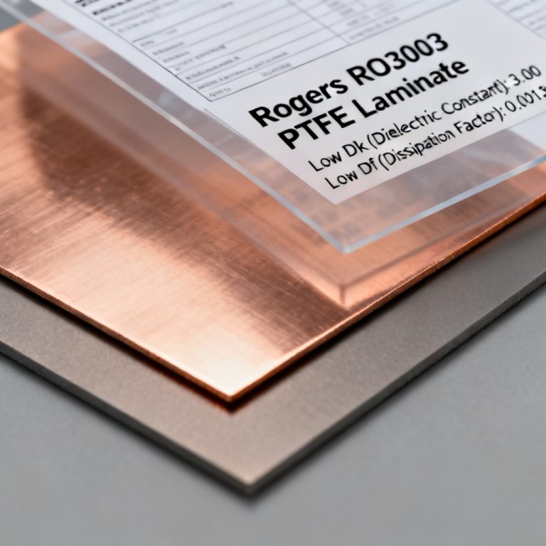
PTFE filled with ceramic powders (e.g., silica, alumina, calcium titanate). Dk can be tuned from 2.2 to 10.2 (common values: 2.6, 3.0, 3.5, 6.15), Df is 0.001–0.003 (low, but higher than pure PTFE). Advantages include tailored Dk for specific impedance, lower CTE (Z-axis < 50 ppm/°C), higher thermal conductivity, and good for mixed-dielectric boards. Disadvantages include higher cost and being more brittle, requiring careful handling. Typical brands: Rogers RO3003, RO4350B (hybrid PTFE/ceramic), Taconic CER-10, Arlon 25N. Best for power amplifiers, filters, and high-reliability multi-layer boards.
Hydrocarbon/Ceramic (PTFE Hybrids)
Blend of PTFE, hydrocarbon resin, and ceramic fillers. These offer a balance between RF performance and FR-4-like processing. Dk is 3.0–3.7 (common), Df is 0.001–0.003. Advantages include being cheaper than pure PTFE, better dimensional stability, and processing on standard FR-4 lines (with minor adjustments). Disadvantages include higher loss than PTFE-only laminates; Dk is less stable with temperature. Typical brands: Rogers RO4000 series (e.g., RO4350B), Isola Astra MT. Best for cost-sensitive high-volume applications, 5G small cells, and automotive radar.
Design Considerations for PTFE PCBs
Designing with PTFE requires a different mindset than FR-4. Here are the essential guidelines from leading industry experts.
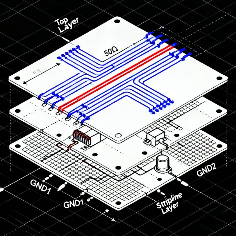
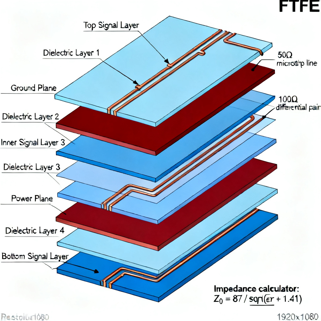
Stackup and Impedance Control
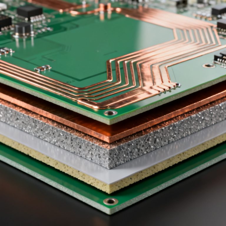
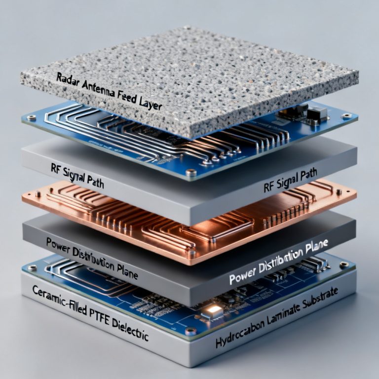
Use a consistent Dk value. Because PTFE laminates have tight Dk tolerances, you can achieve 50Ω or 100Ω differential impedance with high accuracy. Always simulate with the manufacturer’s Dk at your operating frequency (not at 1 MHz). Avoid glass weave effect for woven glass-reinforced PTFE by using a spread-glass or low-porosity weave. Alternatively, choose ceramic-filled laminates for the most uniform dielectric. Consider mixed-dielectric stackups: many high-performance boards use a PTFE layer for the RF signal layer and FR-4 for the power/ground layers. This saves cost while maintaining RF performance. Use a bonding film (e.g., Rogers 3001, Taconic Bonding Film) to ensure reliable lamination.
Thermal Management
Use thermal vias. Since PTFE has low thermal conductivity, use copper-filled or plated-through vias to transfer heat from high-power components to a metal core or heatsink. Select appropriate copper weight. For power applications, use 2 oz or heavier copper to reduce resistive losses, but be aware that thick copper on PTFE can cause stress during thermal cycling. Consider metal-backed PTFE. For high-power amplifiers, use a PTFE laminate bonded to an aluminum or copper baseplate. This provides excellent heat dissipation and mechanical rigidity.
Via and Pad Design
Use laser-drilled microvias. For high-density designs, use laser drilling for small vias (≤ 0.15 mm) in PTFE. Mechanical drilling of small holes can cause burrs or delamination. Avoid via-in-pad without filling. If you place a via in a pad, fill it with non-conductive epoxy or copper. Unfilled vias can wick solder away from the pad during reflow, causing cold joints. Use annular ring sizing. For plated through-holes, use an annular ring diameter at least 0.15 mm larger than the hole size to account for PTFE’s slight movement during lamination.
Manufacturing & Processing Challenges
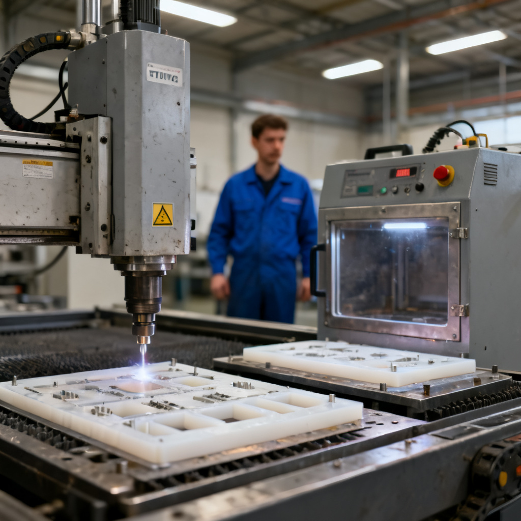
PTFE is notoriously difficult to process. Here are the key challenges and solutions from leading PCB fabricators.
Drilling
PTFE is soft and gummy, causing burrs, smearing, and poor hole quality. Use high-speed spindles (80,000–120,000 RPM) with new carbide drills. Use a backup material (e.g., aluminum entry board) to reduce burrs. For ceramic-filled PTFE, use diamond-coated drills. Feed rate: 0.05–0.1 mm/rev; chip load: 0.01–0.02 mm/rev. Use short drill life (e.g., 500–1000 hits) before replacing.
Plating
PTFE is hydrophobic, making it difficult for electroless copper to adhere to hole walls. Use a plasma desmear process (oxygen/argon plasma) to etch the PTFE surface and create micro-roughness for adhesion. Alternatively, use a sodium etch for chemical roughening. Do not use standard FR-4 desmear chemistry; it will not work on PTFE.
Etching & Solder Mask
PTFE can swell or distort during wet processing. Use a tight control on etching chemistry (e.g., cupric chloride) and temperature (≤ 50°C). For solder mask, use a UV-curable liquid mask specifically designed for PTFE (e.g., Taiyo PSR-4000). Avoid dry-film masks as they may not adhere well. Many PTFE boards are used without solder mask to avoid added loss; instead, use a conformal coating.
Lamination
PTFE has a high melt viscosity and does not flow like FR-4 prepreg. Use a slow ramp-up temperature profile (e.g., 2–5°C/min) to 370–400°C under high pressure (200–400 psi). Use a vacuum lamination press to avoid voids. Bonding films (e.g., Rogers 3001) are essential for multi-layer boards.
Top PTFE Laminate Manufacturers & Product Selection Guide
Based on the most authoritative industry sources, here are the leading manufacturers and their key product lines.
Rogers Corporation
- RT/duroid 5880: Pure PTFE, Dk 2.2, Df 0.0004. Best for >50 GHz.
- RT/duroid 5870: Woven glass-reinforced, Dk 2.33, Df 0.0012. Good for multi-layer boards.
- RO3003: Ceramic-filled, Dk 3.0, Df 0.0013. Excellent for power amplifiers.
- RO4350B: Hydrocarbon/ceramic hybrid, Dk 3.48, Df 0.003. Cost-effective for 5G.
- RO4000 LoPro: Improved surface roughness for lower loss.
Taconic
- TLY-5: Pure PTFE, Dk 2.2, Df 0.0009. Excellent for low-loss applications.
- RF-35: Woven glass-reinforced, Dk 3.5, Df 0.002. Good for antenna arrays.
- CER-10: Ceramic-filled, Dk 10.0, Df 0.0025. For high-Dk needs.
- TSM-DS3: High-speed digital laminate, Dk 3.0, Df 0.0015.
Isola
- I-Tera MT: Woven glass-reinforced PTFE, Dk 3.45, Df 0.002. For high-speed digital.
- Astra MT: Hydrocarbon/ceramic, Dk 3.0, Df 0.0017. Low-loss for aerospace.
- Tachyon 100G: Ultra-low-loss, Dk 3.0, Df 0.001. For 100G+ applications.
Arlon (Now part of Rogers)
- CuClad 217: Pure PTFE, Dk 2.17, Df 0.0009. For microwave circuits.
- 25N: Ceramic-filled, Dk 3.38, Df 0.0025. For power and RF.
Cost vs. Performance Trade-offs
Selecting a PTFE laminate is a balance between electrical performance, manufacturability, and cost. Here is a practical guide:
| Application | Recommended Laminate | Cost Factor (vs. FR-4) | Key Benefit |
|---|---|---|---|
| < 10 GHz, low-volume | RO4350B or RF-35 | 3–5x | Good balance of loss and cost |
| 10–30 GHz, moderate volume | RO3003 or I-Tera MT | 5–8x | Low loss, stable Dk |
| 30–100 GHz, high-reliability | RT/duroid 5880 or TLY-5 | 8–12x | Ultra-low loss |
| High-power, > 50W | RO3003 with metal backing | 10–15x | Thermal management |
| Mixed-dielectric (RF + digital) | RO3003 + FR-4 stackup | 6–10x | Cost savings |
Note: Prices vary by thickness, copper weight, and volume. Always request a quote from multiple suppliers.
Testing & Quality Assurance for PTFE PCBs
To ensure your PTFE PCB meets specifications, perform these tests (per IPC-6012 and IPC-4103 standards):
- Impedance Testing: Use TDR (Time Domain Reflectometry) to verify impedance on every production panel. Target tolerance: ±5% for RF boards.
- Dielectric Constant Verification: Use a resonant cavity method or split-cylinder resonator to measure Dk at the target frequency.
- Peel Strength Test: Measure copper peel strength per IPC-TM-650 (method 2.4.8). Acceptable: >6 lb/in for filled PTFE.
- Thermal Cycling: Perform 100 cycles from -55°C to +125°C to check for delamination or via cracks.
- Moisture Sensitivity: Test per IPC/JEDEC J-STD-020 for moisture absorption and reflow survivability.
Frequently Asked Questions (FAQ)
Can I use standard FR-4 PCB fabrication processes for PTFE?
No. PTFE requires specialized drilling, plasma desmear, and lamination processes. Most standard FR-4 shops cannot handle PTFE. Always use a fabricator certified for high-frequency materials.
How do I prevent PTFE from absorbing moisture?
PTFE itself absorbs almost no moisture. However, the glass reinforcement or fillers can. Use a sealed edge (e.g., copper pour) or a conformal coating to prevent moisture ingress at the board edges.
What is the shelf life of PTFE laminates?
Properly stored PTFE laminates (in original packaging, away from UV and moisture) have a shelf life of 12–24 months. After that, copper adhesion may degrade.
Is PTFE recyclable?
PTFE is not biodegradable and is difficult to recycle. Some manufacturers offer take-back programs. For eco-friendly designs, consider halogen-free alternatives like Rogers RO4000 LoPro.
Conclusion: Partner with a PTFE PCB Expert
PTFE laminates are the backbone of modern high-frequency electronics, but they demand expertise in material selection, design, and manufacturing. By understanding the properties of pure PTFE, woven glass-reinforced, ceramic-filled, and hybrid laminates, you can make informed decisions that balance performance, cost, and reliability.
At [Your Company Name], we specialize in low-loss, high-frequency PCB manufacturing. Our team has deep experience with Rogers, Taconic, Isola, and Arlon materials, and we offer:
- Design for Manufacturability (DFM) reviews to optimize your PTFE board for production.
- Plasma desmear and advanced plating for reliable copper adhesion.
- Tight impedance control (±3% on critical traces).
- Fast turnaround for prototypes and medium-volume production.
Ready to build your next high-frequency PCB? [Contact us today] for a free material consultation and quote. Let our expertise ensure your PTFE board delivers the signal integrity your design demands.
This guide is based on the most authoritative industry sources, including Rogers Corporation, Taconic, Isola, and IPC standards. For the latest material data sheets, visit the respective manufacturer websites.