Selecting the right high-performance PCB materials defines the success of advanced RF, microwave, and power electronics. In an era where performance dictates market leadership, the printed circuit board (PCB) is no longer just a connectivity platform—it is a critical component that directly determines signal integrity, thermal management, and long-term system reliability. Whether you are designing advanced driver-assistance systems operating at 77 GHz, satellite communication hardware, or high-power GaN-based power amplifiers, the days of relying on standard FR-4 are over.
At the upper echelon of PCB design, three high-performance PCB materials platforms dominate: Rogers high-frequency laminates, specialty PTFE-based composites, and ceramic substrates. Each has been engineered to solve specific physical limitations that conventional materials cannot overcome. Understanding their chemistry, electromagnetic properties, and thermal behavior is the first step toward making an informed choice that will define your product’s success.
This guide consolidates essential knowledge from material science, manufacturing process know-how, and practical application engineering. You will learn not simply what these high-performance materials are, but why they perform the way they do, how to select between them, and how to optimize your design stackup for both performance and cost.
1. The Limits of Standard FR-4 and the Need for High-Performance PCB Materials
Understanding why high-performance PCB materials are necessary begins with a clear look at standard FR-4. Traditional FR-4 substrates use an epoxy resin matrix reinforced with woven glass fiber. While cost-effective and suitable for digital circuits below a few hundred megahertz, the material properties become severe bottlenecks in high-frequency, high-speed, or high-thermal-load environments.
- Dielectric loss (Df): The epoxy system exhibits a dissipation factor on the order of 0.020 at 10 GHz. At microwave frequencies, this translates into unacceptable signal attenuation, insertion loss, and heat generation.
- Dielectric constant (Dk) instability: FR-4’s Dk varies significantly with temperature and frequency, causing impedance shifts and phase distortion in critical transmission lines.
- Thermal bottleneck: As a thermal insulator with a conductivity of merely ~0.3 W/m·K, FR-4 cannot effectively remove heat from densely packed active components.
- Moisture absorption: Epoxy is hydrophilic, leading to a changing Dk and increased loss in humid environments.
High-performance applications demand high-performance PCB materials with precisely engineered Dk, orders of magnitude lower Df, tailored thermal expansion coefficients, and, where necessary, bulk thermal conductivity that rivals ceramic insulators.
2. Rogers High-Performance PCB Materials: Beyond Standard Composites
Rogers Corporation’s specialty laminates have become the primary reference for RF and microwave designers working with high-performance PCB materials. Unlike FR-4, which relies on epoxy and glass, Rogers laminates are built on ceramics, thermoset hydrocarbons, or PTFE composites—each formulation targeting a specific performance window.
2.1 What Makes Rogers High-Performance PCB Materials Different?
At the chemical level, Rogers high-performance PCB materials replace the loss-prone epoxy backbone with carefully selected filler and resin systems. For example, the widely used RO4000 series employs a hydrocarbon resin system loaded with ceramic particles. This combination yields a material that processes similarly to FR-4 but delivers RF performance that standard epoxy-glass cannot approach. In contrast, the RO3000 series leans on a PTFE matrix blended with ceramic fillers to reach ultra-low loss characteristics.
2.2 Core Performance Advantages
- Extremely Low Dielectric Loss: A representative RO4350B laminate shows a Df of 0.0037 at 10 GHz, compared to the 0.020 of FR-4. This factor alone can make a critical difference in the link budget of a radar or phased array receiver.
- Stable Dielectric Constant: The Dk of Rogers materials exhibits minimal variation across frequency and operating temperature, ensuring phase-stable filter and coupler designs. The narrow Dk tolerance—often as tight as ±0.05—inherently improves impedance control.
- High Thermal Reliability: With glass transition temperatures (Tg) exceeding 280 °C and decomposition temperatures (Td) above 425 °C, the materials withstand multiple lead-free reflow cycles without degradation.
- Low Water Absorption: Compared with FR-4, the moisture uptake is drastically reduced (typically below 0.1%), keeping the Dk stable even in outdoor telecommunications equipment.
2.3 Popular Rogers High-Performance PCB Materials Specifications
The breadth of the Rogers portfolio allows designers to balance electrical performance, mechanical robustness, and cost. The following high-performance PCB materials table distills some of the most frequently specified material types into a comparative overview.
| Material | Type | Dk (typ.) @10 GHz | Df (typ.) @10 GHz | Tg / Td (°C) | CTE z-axis (ppm/°C) | Typical Application Frequency | Key Characteristic |
|---|---|---|---|---|---|---|---|
| RO4003C | Hydrocarbon/Ceramic | 3.38 ± 0.05 | 0.0027 | >280 / >425 | 46 | Up to 6 GHz and beyond | Low loss, FR-4 process compatible |
| RO4350B | Hydrocarbon/Ceramic | 3.48 ± 0.05 | 0.0037 | >280 / >390 | 50 | Up to Ku-band | Balanced cost and RF performance |
| RO3003 | PTFE/Ceramic | 3.00 ± 0.04 | 0.0013 | – / >500 | 24 | mmWave, 77 GHz radar | Ultra-low loss for highest frequencies |
| RO3010 | PTFE/Ceramic | 10.2 ± 0.30 | 0.0022 | – / >500 | 24 | High-Dk miniaturized filters | Compact circuit layouts |
| RT/duroid 5880 | PTFE/Glass | 2.20 ± 0.02 | 0.0009 | – / – | 38 | Ka-band, satellite | Lowest available Df, lightweight |
| RT/duroid 6002 | PTFE/Ceramic | 2.94 ± 0.04 | 0.0012 | – / – | 24 | Phased arrays, aerospace | High mechanical stability |
2.4 Series Selection: RO4000 vs. RO3000 for High-Performance PCBs
A practical decision framework emerges from these high-performance PCB materials categories. The RO4000 series with hydrocarbon ceramic technology is the go-to when you need a significant RF upgrade from FR-4 without abandoning conventional PCB processing. They do not require special through-hole preparation for plating, which keeps manufacturing complexity and cost contained. Choose RO4350B when loss budget is moderate; pick RO4003C for a lower Df while retaining the same fabrication ease. On the other hand, when design frequencies push into the millimeter-wave domain or when every tenth of a decibel counts, the PTFE-based RO3000 family becomes the reference. RO3003, with its Df of 0.0013, is routinely used in 77 GHz automotive radar sensors. The trade-off is that PTFE materials require more sophisticated via-hole processing to ensure reliable copper plating.
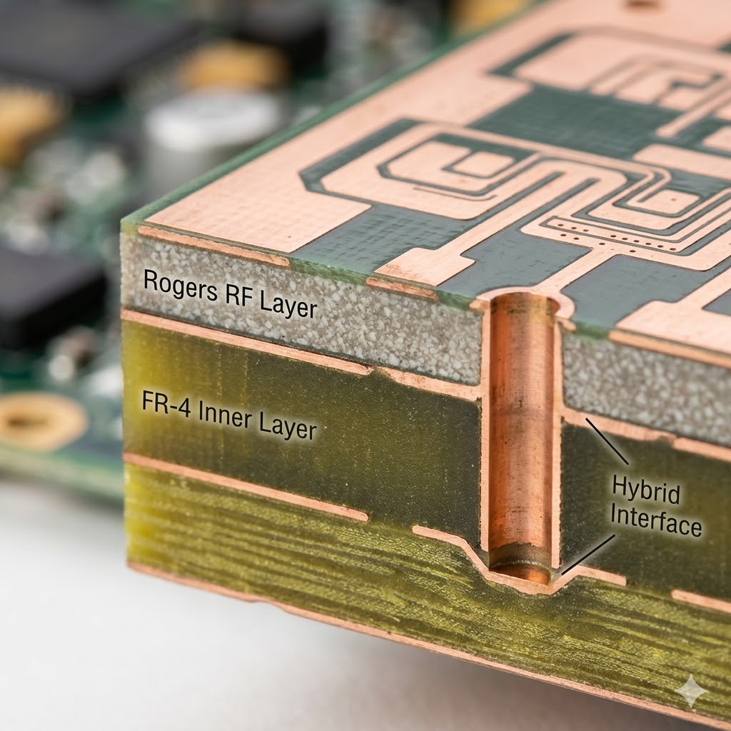
2.5 Hybrid Stackup: Cost Optimization with High-Performance PCB Materials
Using high-performance PCB laminates for an entire multilayer board can be prohibitively expensive in applications where only a few signal layers carry the critical RF paths. The solution is a hybrid stackup. In this architecture, a Rogers laminate (e.g., RO4350B) is used for the outer RF signal layers, while the inner power and digital routing layers are built from standard FR-4. This selective use of specialty materials can reduce overall substrate cost by 30-50% while still delivering the required insertion loss and impedance control. During manufacturing, the process must account for the different dimensional expansion rates between the Rogers and FR-4 layers to keep the composite board flat.
3. PTFE-Based High-Performance PCB Materials: The Science Behind Low Loss
While Rogers Corporations’ proprietary product lines give convenient names to specific high-performance PCB materials, the underlying physics of PTFE (polytetrafluoroethylene) composites deserves a dedicated technical deep dive. Understanding the “formula” explains why these materials perform the way they do and illuminates the trade-offs inherent in their design.
3.1 Pure PTFE: The Starting Point for High-Performance Materials
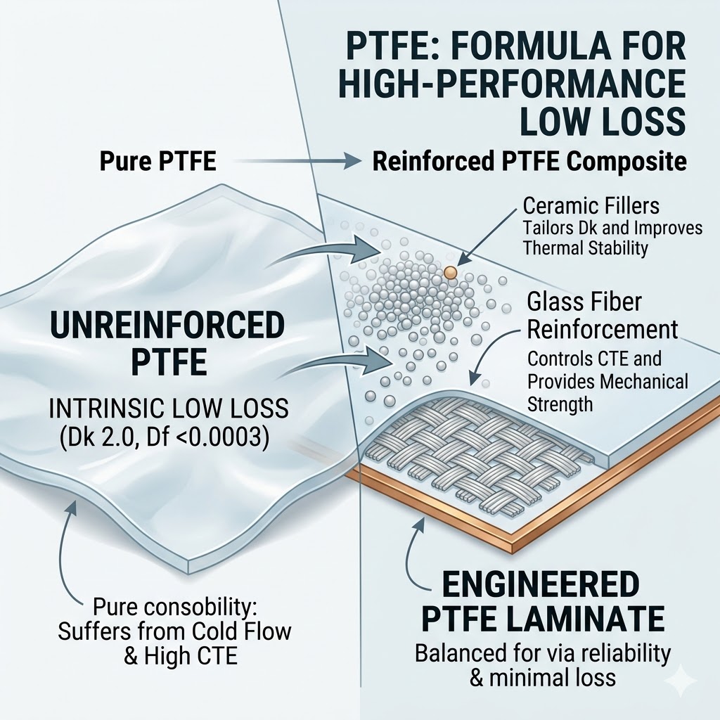
Solid PTFE resin possesses intrinsically outstanding dielectric properties that make it a foundation for high-performance PCB materials. Its non-polar molecular structure gives it a very low dielectric constant of approximately 2.0 and an extremely low dissipation factor near 0.0003. It also features high dielectric strength. If pure PTFE could be used as a straightforward PCB laminate, it would represent the ideal lossless substrate. In reality, pure PTFE is mechanically soft, suffers from cold flow (creep) under mechanical stress, and has a very high coefficient of thermal expansion, making it unreliable for plated through-hole connections.
3.2 The Formula: Fillers and Reinforcement in High-Performance PTFE Laminates
To transform PTFE into a usable commercial laminate within the high-performance PCB materials family, filler systems are introduced. Adding ceramic particles to the PTFE matrix raises the composite’s Dk value in a controlled manner, yielding a range of products with typical Dk values from around 3.0 to well above 10.0. The ceramic reinforcement also improves thermal conductivity and dimensional stability. Some critical formulations incorporate a woven glass cloth primarily to overcome the cold flow problem and provide mechanical robustness for handling and assembly.
3.3 Why Dk Values Range from 3 to Beyond 10
The ability to tailor the Dk in high-performance PCB materials is an essential design tool. As frequency increases, the wavelength of a signal on a transmission line decreases proportionally. Higher Dk materials (10.2) are leveraged to miniaturize circuits—filters, couplers, and antenna feed networks can be shrunk considerably. Lower Dk materials (2.2 to 3.0) are selected when signal propagation speed and latency are the priority, or when a broadband design requires a low dispersion characteristic.
3.4 CTE Matching with Copper as a Reliability Factor
Perhaps the most overlooked aspect of PTFE-based high-performance PCB materials is the deliberate engineering of CTE to match copper. Copper expands at roughly 17 ppm/°C. Through the precise selection and volume fraction of ceramic fillers, laminate manufacturers can bring the composite’s CTE close to that of copper, securing long-term via reliability for demanding aerospace and military applications.
3.5 Design Dk: The Practical Engineering Metric
When simulating a circuit with high-performance PCB materials, the nominal Dk value is only a starting point. The actual Dk is influenced by manufacturing process and glass weave orientation. To address this, laminate suppliers provide a “Design Dk,” a recommended value accounting for process-induced shifts. Based on rigorous testing such as IPC-TM-650 2.5.5.5c, the Design Dk gives engineers a more accurate number for electromagnetic modeling, reducing the number of hardware iterations.
4. Ceramic High-Performance PCB Materials for Thermal Management
While Rogers and PTFE composites solve signal loss and frequency stability problems, a separate class of high-performance PCB materials addresses a different physical bottleneck: extreme heat. High-power LED modules, RF power amplifier pallets, and dense SiC/GaN converter modules generate heat fluxes that overwhelm any organic laminate. Here, the substrate itself must become an efficient thermal conductor.
4.1 The Thermal Limitations of Conventional PCBs
Two common approaches fail under high thermal loads, making high-performance ceramic PCB materials necessary. FR-4, with its ~0.3 W/m·K conductivity, acts as a thermal insulator, causing junction temperature spikes. Metal-core PCBs bond copper to an aluminum plate via a thin dielectric layer, but that layer remains a significant thermal bottleneck with only 1–8 W/m·K. Ceramic substrates circumvent the problem entirely by eliminating the organic dielectric layer.
4.2 Alumina vs. Aluminum Nitride: Ceramic High-Performance PCB Materials Compared
The two primary ceramic high-performance PCB materials dominate high-power electronics, and their differences dictate design decisions.
| Property | Alumina (Al₂O₃) | Aluminum Nitride (AlN) |
|---|---|---|
| Thermal Conductivity | 20–24 W/m·K | 170–230 W/m·K |
| CTE (ppm/°C) | ~6.8–7.2 | ~4.3–4.6 |
| Dielectric Strength | High | High |
| Cost | Moderate; cost-effective for many power applications | Significantly higher; reserved for extreme heat flux scenarios |
| Typical Application | LED lighting, motor drives, moderate power modules | GaN/SiC power converters, RF power amplifiers, high-flux laser diodes |
4.3 Direct Bonded Copper: The Enabling Process for Ceramic High-Performance Materials
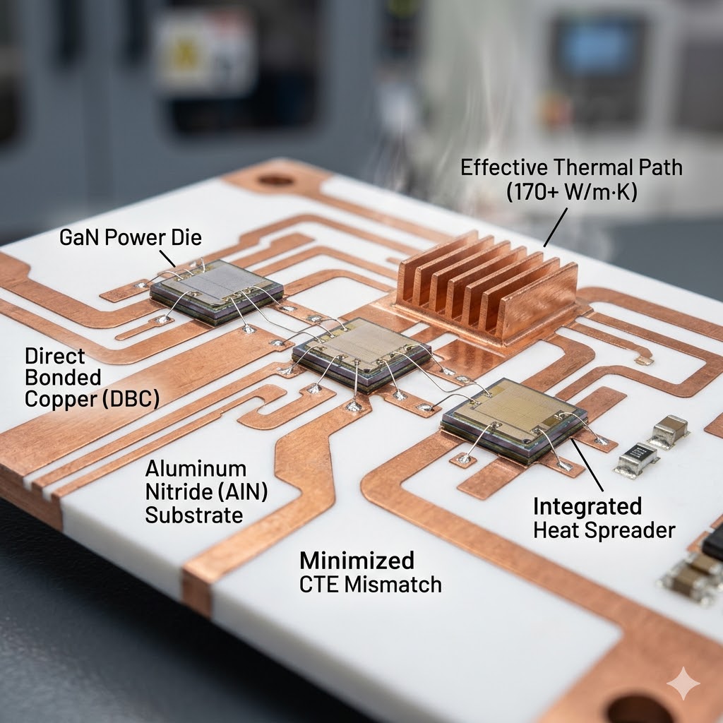
The truly transformative advantage of ceramic high-performance PCB materials lies in Direct Bonded Copper (DBC) technology. In a DBC process, pure copper foil is bonded directly to the ceramic surface without any intermediate organic adhesive. This monolithic-like interface eliminates the thermal bottleneck, so the total thermal resistance of a DBC ceramic board can be 30% to 50% lower than an equivalent MCPCB. The result is dramatically improved power handling and device longevity for high-power designs.
4.4 CTE Compatibility with Wide-Bandgap Semiconductors
Thermal cycling reliability in power modules built on high-performance ceramic PCB materials also depends on mechanical integrity. AlN’s CTE of ~4.5 ppm/°C is remarkably close to that of silicon, SiC, and GaN. This match minimizes thermo-mechanical stress, preventing delamination and solder fatigue over thousands of operational cycles, which is essential as wide-bandgap semiconductors enable system miniaturization at higher temperatures.
4.5 Design Decision Framework for Ceramic High-Performance PCBs
When selecting ceramic high-performance PCB materials, factor in practical guidelines. Select Alumina when your power density is high but cost is a primary consideration, and the thermal conductivity of ~24 W/m·K keeps your junction temperature safe. Choose Aluminum Nitride when the heat flux is so intense that the substrate must actively spread heat laterally, especially in pulsed RF applications and GaN MIMO systems. Be aware that DBC/AMB panels have maximum available sizes, so collaborate with your manufacturer early.
5. High-Performance PCB Material Selection: A Unified Framework
With an understanding of each high-performance PCB material platform, the selection process becomes a systematic comparison of your project’s electrical, thermal, and economic requirements. The following unified framework helps identify the recommended material path.
| Requirement | Recommended High-Performance Material Platform | Rationale |
|---|---|---|
| Low-mid RF (<6 GHz), low loss, easy fabrication | Rogers RO4000 Series (Hydrocarbon/Ceramic) | Processes like FR-4, stable Dk, Df ~0.0037, hybrid stackup saves cost. |
| mmWave, ultra-low loss, phase-sensitive radars | Rogers RO3000 or RT/duroid (PTFE-based) | Df as low as 0.0009, tightly controlled Dk, excellent frequency stability. |
| High-Dk need for circuit miniaturization | RO3010 or loaded PTFE laminates | Dk of 10.2 enables compact filters and antenna networks. |
| High power, continuous heat dissipation, moderate insulation | Alumina DBC substrate | 20+ W/m·K conductivity at competitive cost. |
| Extreme power density, GaN/SiC, highest reliability | Aluminum Nitride DBC/AMB substrate | Over 170 W/m·K, CTE matched to wide-bandgap chips, maximum Rth reduction. |
| Tight budget, only a few RF paths | Hybrid FR-4 + Rogers RO4350B stackup | Performance on critical layers, cost of FR-4 everywhere else. |
6. Manufacturing Expertise for High-Performance PCB Materials
Selecting the right high-performance PCB material is the architectural decision; the build quality turns that decision into a functioning product. Manufacturing high-performance PCBs, especially those involving PTFE laminates or ceramic substrates, requires dedicated process controls. Unlike standard PCB shops that treat these specialty materials as exotic add-ons, our dedicated production lines are built around their specific demands.
- Via Preparation for PTFE: PTFE substrates resist adhesion after drilling. Our specialized plasma etching treatment activates the hole wall, ensuring highly reliable plated copper interconnects in every high-performance PCB.
- Hybrid Lamination Cycle Management: When mixing Rogers and FR-4 in a single stackup, a balanced press cycle accommodates the different rheology of dissimilar prepregs without warp or thickness variation.
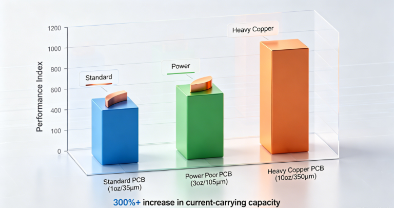
- DBC Cu Thickness Control: For ceramic substrates, controlling copper foil thickness and bond integrity is critical. Our precision process maintains current-carrying capacity and thermal cycling life for ceramic high-performance PCB materials.
Our facility runs standard multilayer FR-4 alongside a dedicated PTFE-capable line with plasma via treatment and precision DBC ceramic assembly for power module integration—providing the complete manufacturing ecosystem that your high-performance PCB design demands.
7. Turn Your Performance Requirements into a Reliable Build
The depth of information presented here reflects the intricacy of modern high-performance electronics. Partner with us to get your high-performance PCB materials implementation right the first time. Submit your design requirements, and our application engineering team will recommend an optimized material stackup, review impedance targets and thermal models, and fabricate your boards with specialist process precision.
Contact Us to Discuss Your High-Performance PCB Project →
Frequently Asked Questions About High-Performance PCB Materials
What are high-performance PCB materials?High-performance PCB materials are advanced substrates such as Rogers laminates, PTFE composites, and ceramic boards that overcome the loss, thermal, and stability limits of FR-4. They are essential for RF, microwave, and high-power electronics where signal integrity and heat dissipation are critical.Why use Rogers materials for high-performance PCBs?Rogers high-performance PCB materials offer ultra-low dissipation factors, stable dielectric constants, and high thermal reliability. They are engineered for radar, satellite, and 5G applications, providing repeatable performance well into the millimeter-wave spectrum.How do ceramic high-performance PCB materials improve thermal management?Ceramic high-performance PCB materials such as AlN and Al₂O₃ act as thermal conductors. Direct Bonded Copper technology eliminates the organic dielectric layer, reducing thermal resistance by up to 50% compared to metal-core boards, making them ideal for GaN and SiC devices.What is a hybrid stackup in high-performance PCBs?A hybrid stackup combines a high-performance material like Rogers on critical RF layers with FR-4 on digital layers to balance cost and performance. It is a widely adopted strategy to reduce total substrate cost while meeting impedance and loss targets.