Phase-stable PCB materials with low Dk shift are critical for radar systems, ensuring signal integrity across temperature and frequency variations. This guide covers material selection, design guidelines, and testing for high-performance radar PCBs.
Why Phase-Stable PCB Materials Matter for Radar Systems
Phase-stable PCB materials directly impact radar beamforming accuracy. In phased array radar, a Dk shift of just 0.1% can cause phase errors of several degrees at Ku-band frequencies, degrading beam pointing and range resolution. For automotive ADAS or defense systems, maintaining phase coherence across thousands of elements demands materials with extremely low Dk drift.
Key Radar Performance Metrics Affected by Dk Stability
- Beam pointing accuracy: Phase errors shift the main lobe direction.
- Angle resolution: Phase noise reduces angular discrimination.
- Range resolution: Phase instability blurs pulse compression.
- Imaging quality: In synthetic aperture radar (SAR), phase errors cause image defocusing.
The Physics of Dk Shift: Temperature, Frequency, and Moisture
Understanding the physics of Dk shift is essential for selecting phase-stable PCB materials. The dielectric constant of a substrate varies with temperature, frequency, and moisture absorption, each affecting radar phase stability differently.
Temperature Coefficient of Dielectric Constant (TCDk)
The Temperature Coefficient of Dielectric Constant (TCDk) measures Dk change per degree Celsius. Standard FR-4 exhibits TCDk of 200–400 ppm/°C, while phase-stable materials achieve <50 ppm/°C, with premium grades below 20 ppm/°C. For radar systems operating from -55°C to +125°C, the material must maintain stable Dk across the entire range.
Three distinct regions exist in the Dk vs. temperature curve: below Tg, Dk decreases slowly; near Tg, a sharp negative spike occurs; above Tg, Dk continues decreasing at a steeper rate. Phase-stable PCB materials minimize these transitions through advanced resin and filler formulations.
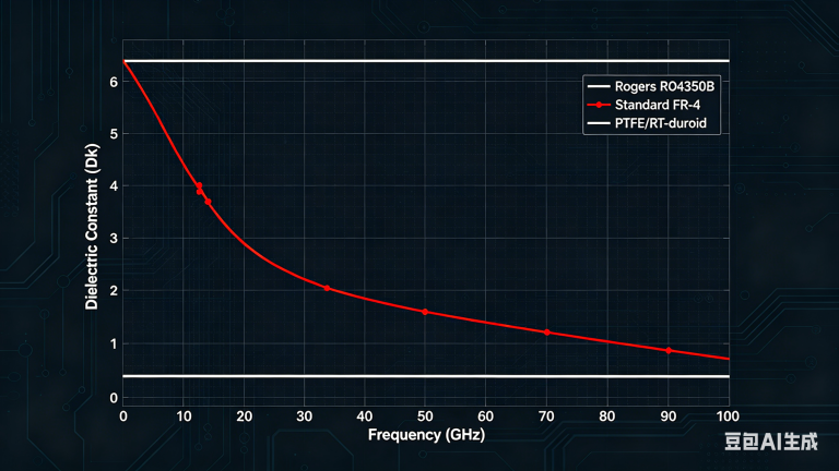
Frequency Dependence of Dk
Dk decreases with increasing frequency due to dipole relaxation. For radar bands, the Dk drop is significant: L-band (1-2 GHz) shows <0.02 drop, while Ku-band (12-18 GHz) can experience 0.12-0.20 drop. Phase-stable materials use low-polarity resins (PTFE, PPO, PPE) and ceramic fillers to minimize this frequency-induced Dk dispersion.
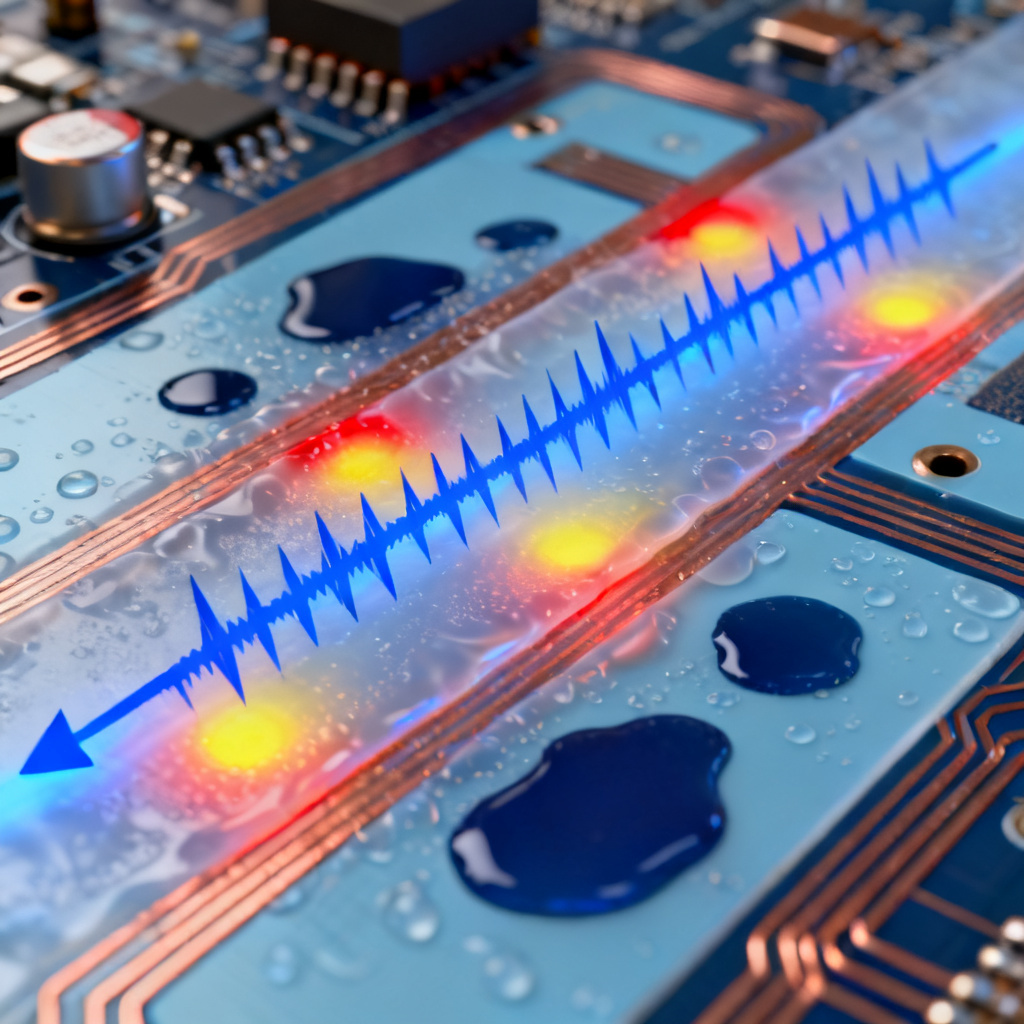
Moisture Absorption and Its Effect on Dk
Water has a Dk of ~80 at 25°C. Even 0.1% moisture absorption by weight can increase effective Dk by 0.05-0.15 at microwave frequencies. Critical moisture absorption thresholds: standard FR-4 absorbs 0.6-1.0%, while phase-stable PTFE/ceramic materials absorb <0.05%. Moisture-induced Dk shift is reversible upon baking, but hysteresis can accumulate over thermal cycles.
Material Families for Phase-Stable Radar PCBs
Selecting the right phase-stable PCB materials involves understanding three primary families: PTFE-based composites, hydrocarbon/ceramic laminates, and advanced thermoset resins. Each offers distinct advantages for radar applications.
1. PTFE-Based Composites with Ceramic Fillers
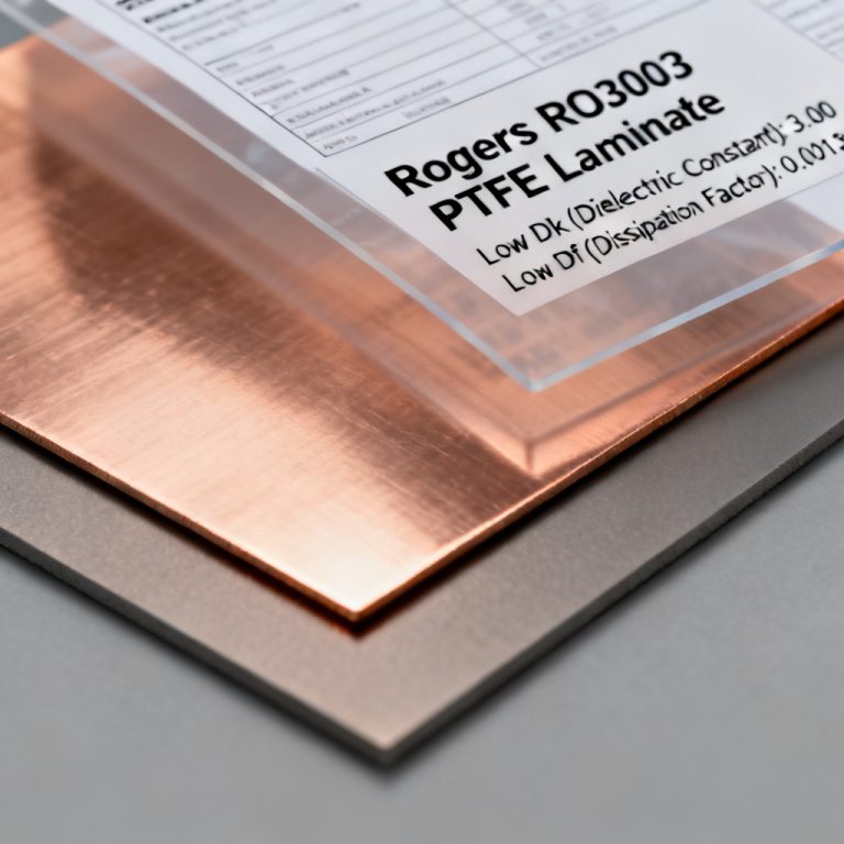
PTFE (polytetrafluoroethylene) offers the lowest dielectric loss (Df < 0.002) and excellent Dk stability. Ceramic-filled PTFE composites address thermal expansion issues.
| Product | Dk @10 GHz | TCDk (ppm/°C) | Moisture Absorption (%) | Df @10 GHz |
|---|---|---|---|---|
| Rogers RO3003™ | 3.00 | -45 | 0.04 | 0.0013 |
| Rogers RO3010™ | 10.2 | -40 | 0.04 | 0.0022 |
| Taconic TLY-5A | 2.17 | -20 | 0.02 | 0.0009 |
| Arlon 25N | 3.38 | -30 | 0.04 | 0.0015 |
Advantages: Excellent Dk stability (TCDk < 50 ppm/°C), very low moisture absorption (<0.05%), superior high-frequency performance up to 100 GHz. Limitations: Higher cost, requires specialized processing (plasma treatment for adhesion).
2. Hydrocarbon/Ceramic (HC) Laminates
Hydrocarbon resin systems (PPO or PPE based) combined with ceramic fillers offer a balance of phase stability, cost, and processability. These are common for automotive radar and 5G infrastructure.
| Product | Dk @10 GHz | TCDk (ppm/°C) | Moisture Absorption (%) | Df @10 GHz |
|---|---|---|---|---|
| Rogers RO4350B™ | 3.48 | +50 | 0.06 | 0.0037 |
| Rogers RO4835™ | 3.48 | +40 | 0.05 | 0.0035 |
| Isola I-Tera MT40 | 3.45 | +30 | 0.05 | 0.0030 |
| Panasonic Megtron 6 | 3.65 | +25 | 0.08 | 0.0040 |
Advantages: Good Dk stability (TCDk 25-50 ppm/°C), lower cost than PTFE, compatible with standard FR-4 processing. Limitations: Higher Df than PTFE (0.002-0.004), moisture absorption 0.05-0.15%.
3. Advanced Thermoset Resins (BT, Modified Epoxy)
For applications requiring high Tg and moderate phase stability, bismaleimide triazine (BT) and modified epoxy systems bridge the gap between FR-4 and high-performance laminates.
| Product | Dk @10 GHz | TCDk (ppm/°C) | Moisture Absorption (%) | Df @10 GHz |
|---|---|---|---|---|
| Mitsubishi BT-H | 4.1 | +80 | 0.15 | 0.008 |
| Hitachi MCL-BT | 4.3 | +70 | 0.18 | 0.009 |
| Nelco N7000 | 3.7 | +60 | 0.12 | 0.007 |
Advantages: High Tg (180-250°C), lower cost than PTFE and HC, good dimensional stability. Limitations: Higher TCDk (60-100 ppm/°C), higher Df (0.005-0.010), moisture absorption 0.1-0.3%.
Quantitative Comparison of Phase-Stable PCB Materials
| Material | Dk @10 GHz | TCDk (ppm/°C) | Moisture Absorption (%) | Df @10 GHz | Tg (°C) | Relative Cost |
|---|---|---|---|---|---|---|
| FR-4 (standard) | 4.3-4.5 | 200-400 | 0.6-1.0 | 0.020-0.025 | 130-150 | 1x |
| High-Tg FR-4 | 4.2-4.4 | 150-250 | 0.3-0.6 | 0.015-0.020 | 170-180 | 1.5x |
| BT (Mitsubishi) | 4.1 | 80 | 0.15 | 0.008 | 180 | 2x |
| HC (RO4350B) | 3.48 | 50 | 0.06 | 0.0037 | 280 | 4x |
| PTFE/Ceramic (RO3003) | 3.00 | -45 | 0.04 | 0.0013 | >500 | 8x |
| PTFE/Ceramic (TLY-5A) | 2.17 | -20 | 0.02 | 0.0009 | >500 | 10x |
Designing for Phase Stability: Practical Guidelines
Effective design with phase-stable PCB materials requires careful material selection by radar band, copper foil treatment, and multilayer stackup optimization.
1. Material Selection by Radar Band
Automotive Radar (77-81 GHz): Primary choice is RO3003 or RO4835 for Dk stability and low loss; avoid BT or modified epoxies due to high Dk drift at mmWave.
Defense Phased Array (X-band, Ku-band): Primary choice is RO3003 or RO3010 for high-Dk power dividers; TCDk must be <30 ppm/°C for wideband operation.
Weather Radar (S-band, C-band): Primary choice is RO4350B or I-Tera MT40; moisture resistance is paramount for outdoor installations.
5G mmWave (24-40 GHz): Primary choice is RO4835 for improved moisture resistance; Dk frequency stability critical across 5G bands.
2. Copper Foil Surface Treatment
The copper-substrate interface contributes to phase instability through surface roughness and oxidation. Use RTF or VLP copper for frequencies above 10 GHz, specify passivation layers to prevent oxidation, and for PTFE materials use electrodeposited copper with low roughness (Rz < 2 μm).
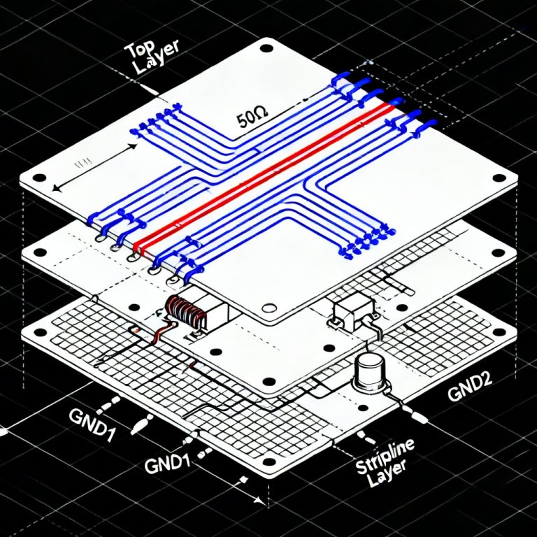
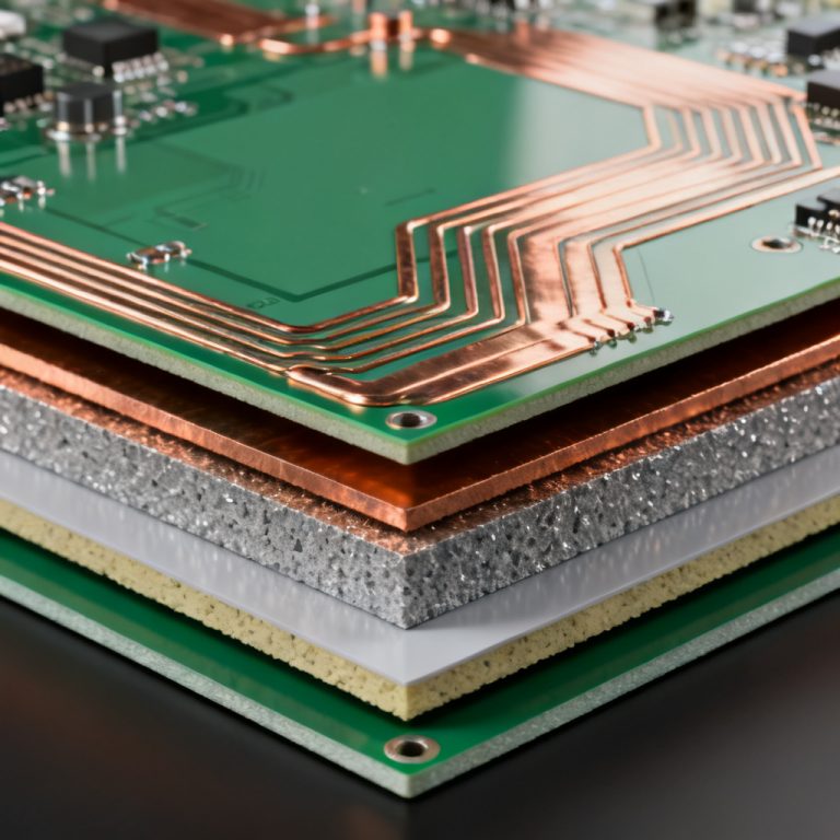
3. Multilayer Stackup Design
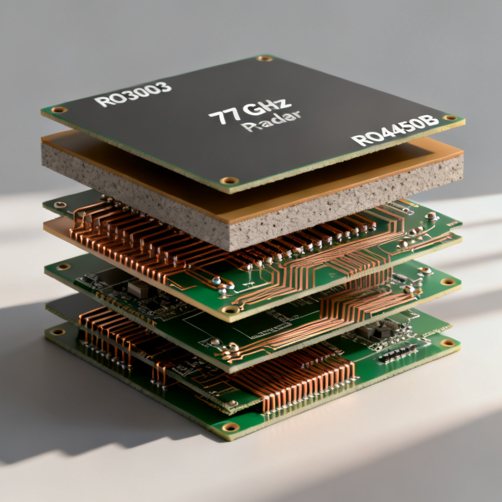
Phase stability in multilayer boards requires Dk matching between core and prepreg, use of spread glass for improved Dk uniformity, and resin content of 45-55% for balanced performance. Example stackup for 77 GHz radar: RO3003 core (5 mil), RO4450B prepreg, RO3003 core (10 mil), RO4450B prepreg, RO3003 core (5 mil).
4. Thermal Management for Phase Stability
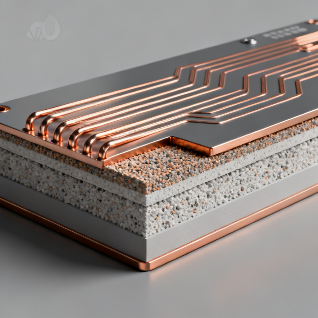
Heat from high-power amplifiers directly affects Dk. Use thermal vias, metal core PCBs, embedded heat sinks, and materials with high thermal conductivity (e.g., RO3003 at 0.50 W/mK vs. FR-4 at 0.25 W/mK).
Manufacturing Considerations for Phase-Stable PCBs
Manufacturing phase-stable PCB materials requires modified drilling, lamination, and impedance control processes to preserve Dk stability.
1. Drilling and Plating
PTFE and HC materials need drill speeds of 80-120 kRPM for PTFE and 60-80 kRPM for HC, with feed rates of 0.5-1.0 mil/rev and 1.0-1.5 mil/rev respectively. Use aluminum entry and phenolic exit materials, and specific etchants for PTFE plating.
2. Lamination
Phase-stable materials have higher melt viscosity: use 300-400 psi for PTFE, 200-300 psi for HC, temperature ramp of 2-5°C/min, controlled cooling to prevent warpage, and vacuum lamination to eliminate voids.
3. Impedance Control
For radar applications, impedance tolerance must be ±2% or better. Specify material Dk tolerance ±0.05, account for etch factor, include impedance test coupons, and use TDR verification for final qualification.
Testing and Validation of Phase Stability
Rigorous testing of phase-stable PCB materials ensures Dk stability meets radar system requirements. Key methods include clamped stripline resonator, split post dielectric resonator, and full-sheet resonance.
1. Dk Measurement Methods
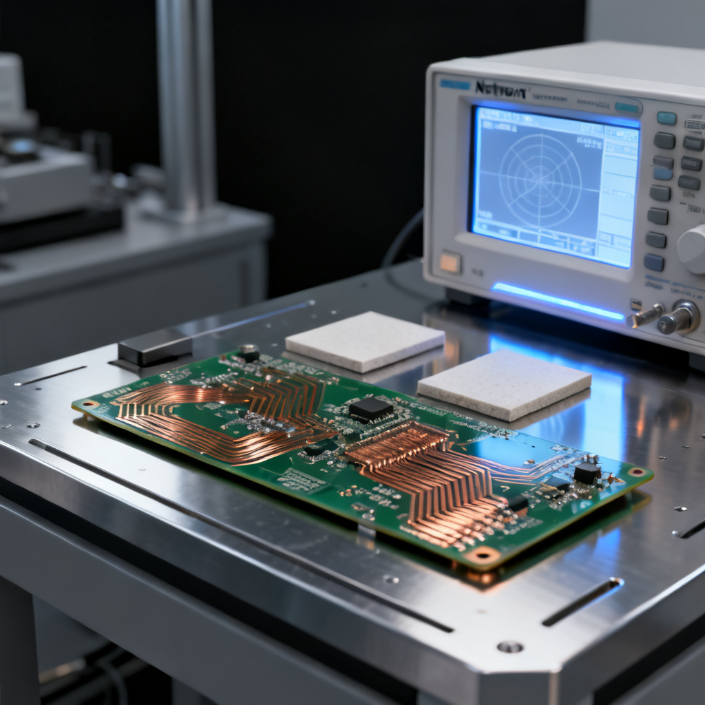
Clamped Stripline Resonator (CSTM): Most accurate for Dk and Df at specific frequencies, accuracy ±0.01 for Dk. Split Post Dielectric Resonator (SPDR): Non-destructive, suitable for 1-20 GHz, accuracy ±0.02. Full-Sheet Resonance (FSR): Measures Dk across entire panel for uniformity, accuracy ±0.05.
2. Phase Stability Testing
Temperature Cycling: -55°C to +125°C, 10 cycles minimum, acceptable Dk shift <0.05. Moisture Resistance: 85°C/85% RH for 168 hours, acceptable Dk shift <0.03. Aging Test: 125°C for 1000 hours, acceptable Dk shift <0.02.
3. Production Quality Assurance
Verify Dk and TCDk per lot using CSTM or SPDR, measure impedance on test coupons every panel, perform thermal cycling on sample boards per batch, and provide Dk vs. temperature curves for each material lot.
Real-World Case Studies
Case studies demonstrate how phase-stable PCB materials solve real radar phase drift problems.
Case 1: Automotive Radar Module (77 GHz)
Problem: Phase drift of 15° over -40°C to +105°C caused beam pointing errors. Solution: Switched from RO4350B (TCDk 50 ppm/°C) to RO3003 (TCDk -45 ppm/°C). Phase drift reduced to 3° over the same temperature range. Additional moisture barrier coating eliminated humidity effects.
Case 2: Defense Phased Array (X-band)
Problem: Dk variation across large panels (24″ x 18″) caused element-to-element phase mismatch. Solution: Specified RO3003 with Dk tolerance ±0.04 and used spread glass prepreg (RO4450F). Implemented full-sheet resonance testing for every panel. Phase mismatch reduced from 12° to 2° RMS.
Case 3: Weather Radar Receiver (S-band)
Problem: Moisture absorption in FR-4 caused gradual Dk increase over 6 months, degrading calibration. Solution: Replaced FR-4 with I-Tera MT40 (moisture absorption 0.05%). Applied conformal coating to exposed surfaces. Dk drift reduced from 0.15 to <0.02 over 12 months.
Future Trends in Phase-Stable Materials
Emerging phase-stable PCB materials include Liquid Crystal Polymer (LCP) for mmWave radar, Low-Temperature Co-fired Ceramic (LTCC) for frequencies up to 200 GHz, nanocomposite resins targeting TCDk below 10 ppm/°C, and AI-optimized material design for custom radar bands.
Frequently Asked Questions About Phase-Stable PCB Materials
What are phase-stable PCB materials?
Phase-stable PCB materials are substrates engineered to maintain a consistent dielectric constant (Dk) across temperature, frequency, and humidity variations, minimizing phase errors in radar systems.
Why is low Dk shift important for radar systems?
Low Dk shift is critical for radar systems because even small Dk variations cause phase errors that degrade beamforming accuracy, range resolution, and target detection performance.
Which phase-stable PCB material is best for 77 GHz automotive radar?
For 77 GHz automotive radar, RO3003 (PTFE/ceramic) is the best phase-stable PCB material due to its low TCDk (-45 ppm/°C), very low moisture absorption (0.04%), and excellent high-frequency performance.
How do I test phase stability of PCB materials?
Phase stability of PCB materials is tested using temperature cycling (-55°C to +125°C), moisture resistance (85°C/85% RH), and aging tests (125°C for 1000 hours), with Dk measured via clamped stripline resonator or split post dielectric resonator.
What is the difference between TCDk and Dk tolerance?
TCDk (Temperature Coefficient of Dielectric Constant) measures how Dk changes with temperature in ppm/°C, while Dk tolerance specifies the manufacturing variation of Dk at a single temperature (e.g., ±0.04). Both are critical for phase-stable PCB materials.
“`